PDF : Goxs-1312-40d-sfp-1-25g-module-40km-single-mode
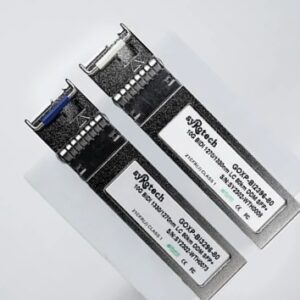
GOXS-1312-40D
1.25Gbps SFP Optical Transceiver, 40km Reach
Features
- Dual data-rate of 25Gbps/1.063Gbps operation
- 1310nm DFB laser and PIN photo detector for 40km transmission
- Compliant with SFP MSA and SFF-8472 with duplex LC receptacle
- Digital Diagnostic Monitoring:
Internal Calibration or External Calibration
- Compatible with SONET OC-24-LR
- Compatible with RoHS
l +3.3V single power supply
- Operating case temperature: Standard : 0 to +70°C Industrial : -40 to +85°C
Applications
- Gigabit Ethernet
- Fiber Channel
- Switch to Switch interface
- Switched backplane applications
- Router/Server interface
- Other optical transmission systems
Description
The SFP transceivers are high performance, cost effective modules supporting dual data-rate of 1.25Gbps/1.0625Gbps and 40km transmission distance with SMF.
The transceiver consists of three sections: a DFB laser transmitter, a PIN photodiode integrated with a trans-impedance preamplifier (TIA) and MCU control unit. All modules satisfy class I laser safety requirements.
Absolute Maximum Ratings
Table 1 – Absolute Maximum Ratings
| Parameter | Symbol | Min | Max | Unit |
| Supply Voltage | Vcc | -0.5 | 4.5 | V |
| Storage Temperature | Ts | -40 | +85 | °C |
| Operating Humidity | – | 5 | 85 | % |
Recommended Operating Conditions
Table 2 – Recommended Operating Conditions
| Parameter | Symbol | Min | Typical | Max | Unit | |
| Operating Case Temperature | Standard | Tc | 0 | +70 | °C | |
| Industrial | -40 | +85 | °C | |||
| Power Supply Voltage | Vcc | 3.13 | 3.3 | 3.47 | V | |
| Power Supply Current | Icc | 300 | mA | |||
| Data Rate | 1.25 | Gbps | ||||
Optical and Electrical Characteristics
GOCS-1312-40 : (DFB and PIN, 1310nm, 40km Reach)
Table 3 – Optical and Electrical Characteristics
| Parameter | Symbol | Min | Typical | Max | Unit | Notes | ||
| Transmitter | ||||||||
| Centre Wavelength | λc | 1260 | 1310 | 1360 | nm | |||
| Spectral Width (-20dB) | ∆λ | 1 | nm | |||||
| Side Mode Suppression Ratio | SMSR | 30 | dB | |||||
| Average Output Power | Pout | -5 | 2 | dBm | 1 | |||
| Extinction Ratio | ER | 9 | dB | |||||
| Optical Rise/Fall Time (20%~80%) | tr/tf | 0.26 | ns | |||||
| Data Input Swing Differential | VIN | 400 | 1800 | mV | 2 | |||
| Input Differential Impedance | ZIN | 90 | 100 | 110 | Ω | |||
| TX Disable | Disable | 2.0 | Vcc | V | ||||
| Enable | 0 | 0.8 | V | |||||
| TX Fault | Fault | 2.0 | Vcc | V | ||||
| Normal | 0 | 0.8 | V | |||||
| Receiver | ||||||||
| Centre Wavelength | λc | 1260 | 1360 | nm | ||||
| Receiver Sensitivity | -23 | dBm | 3 | |||||
| Receiver Overload | -3 | dBm | 3 | |||||
| LOS De-Assert | LOSD | -24 | dBm | |||||
| LOS Assert | LOSA | -35 | dBm | |||||
| LOS Hysteresis | 1 | 4 | dB | |||||
| Data Output Swing Differential | Vout | 370 | 1800 | mV | 4 | |||
| LOS | High | 2.0 | Vcc | V | ||||
| Low | 0.8 | V | ||||||
Notes:
- The optical power is launched into
- PECL input, internally AC-coupled and
- Measured with a PRBS 27-1 test pattern @1250Mbps, BER ≤1×10-12.
- Internally AC-coupled.
Timing and Electrical
Table 4 – Timing and Electrical
| Parameter | Symbol | Min | Typical | Max | Unit |
| Tx Disable Negate Time | t_on | 1 | ms | ||
| Tx Disable Assert Time | t_off | 10 | µs | ||
| Time To Initialize, including Reset of Tx Fault | t_init | 300 | ms | ||
| Tx Fault Assert Time | t_fault | 100 | µs | ||
| Tx Disable To Reset | t_reset | 10 | µs | ||
| LOS Assert Time | t_loss_on | 100 | µs | ||
| LOS De-assert Time | t_loss_off | 100 | µs | ||
| Serial ID Clock Rate | f_serial_clock | 400 | KHz | ||
| MOD_DEF (0:2)-High | VH | 2 | Vcc | V | |
| MOD_DEF (0:2)-Low | VL | 0.8 | V |
Diagnostics
Table 5 – Diagnostics Specification
| Parameter | Range | Unit | Accuracy | Calibration |
| Temperature | 0 to +70 | °C | ±3°C | Internal / External |
| -40 to +85 | ||||
| Voltage | 3.0 to 3.6 | V | ±3% | Internal / External |
| Bias Current | 0 to 100 | mA | ±10% | Internal / External |
| TX Power | -5 to +2 | dBm | ±3dB | Internal / External |
| RX Power | -23 to -3 | dBm | ±3dB | Internal / External |
Pin Descriptions
| Pin | Signal Name | Description | Plug Seq. | Notes |
| 1 | VEET | Transmitter Ground | 1 | |
| 2 | TX FAULT | Transmitter Fault Indication | 3 | Note 1 |
| 3 | TX DISABLE | Transmitter Disable | 3 | Note 2 |
| 4 | MOD_DEF(2) | SDA Serial Data Signal | 3 | Note 3 |
| 5 | MOD_DEF(1) | SCL Serial Clock Signal | 3 | Note 3 |
| 6 | MOD_DEF(0) | TTL Low | 3 | Note 3 |
| 7 | Rate Select | Not Connected | 3 | |
| 8 | LOS | Loss of Signal | 3 | Note 4 |
| 9 | VEER | Receiver ground | 1 | |
| 10 | VEER | Receiver ground | 1 | |
| 11 | VEER | Receiver ground | 1 | |
| 12 | RD- | Inv. Received Data Out | 3 | Note 5 |
| 13 | RD+ | Received Data Out | 3 | Note 5 |
| 14 | VEER | Receiver ground | 1 | |
| 15 | VCCR | Receiver Power Supply | 2 | |
| 16 | VCCT | Transmitter Power Supply | 2 | |
| 17 | VEET | Transmitter Ground | 1 | |
| 18 | TD+ | Transmit Data In | 3 | Note 6 |
| 19 | TD- | Inv. Transmit Data In | 3 | Note 6 |
| 20 | VEET | Transmitter Ground | 1 |
Notes:
Plug Seq.: Pin engagement sequence during hot plugging.
- TX Fault is an open collector output, which should be pulled up with a 4.7k~10kΩ resistor on the host board to a voltage between 2.0V and Vcc+0.3V. Logic 0 indicates normal operation; Logic 1 indicates a laser fault of some kind. In the low state, the output will be pulled to less than 8V.
- TX Disable is an input that is used to shut down the transmitter optical output. It is pulled up within the module with a 7k~10kΩ resistor. Its states are:
Low (0 to 0.8V): Transmitter on
(>0.8V, < 2.0V): Undefined
High (2.0 to 3.465V): Transmitter Disabled Open: Transmitter Disabled
- Mod-Def 0,1,2. These are the module definition They should be pulled up with a 4.7k~10kΩ resistor on the host board. The pull-up voltage shall be VccT or VccR.
Mod-Def 0 is grounded by the module to indicate that the module is present Mod-Def 1 is the clock line of two wire serial interface for serial ID
Mod-Def 2 is the data line of two wire serial interface for serial ID
- LOS is an open collector output, which should be pulled up with a 4.7k~10kΩ Pull up voltage between 2.0V and Vcc+0.3V. Logic 1 indicates loss of signal; Logic 0 indicates normal operation. In the low state, the output will be pulled to less than 0.8V.
- RD-/+: These are the differential receiver outputs. They are internally AC-coupled 100 differential lines which should be terminated with 100Ω (differential) at the user
- TD-/+: These are the differential transmitter They are internally AC-coupled, differential lines with 100Ω differential termination inside the module.
For more information please contact
Whatsapp/Call :8527090690